- Our Technology
- Toolkits
- Toolkit: 3D Blade Design
3D Blade Design
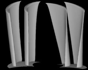
Our turbomachinery design toolkits include one on 3D blade design...
- Toolkit: Meanline Design
Meanline Design
TURBOdesign Suite provides tools to designers to put them in direct control of aerodynamic design to streamline every step of the design process for turbomachinery components.
Lorem ipsum dolor sit amet, consectetur adipiscing elit. Suspendisse varius enim in eros elementum tristique.
Lorem ipsum dolor sit amet, consectetur adipiscing elit. Suspendisse varius enim in eros elementum tristique. Duis cursus, mi quis viverra ornare, eros dolor interdum nulla, ut commodo diam libero vitae erat. Aenean faucibus nibh et justo cursus id rutrum lorem imperdiet. Nunc ut sem vitae risus tristique posuere.
- Toolkit: Volute / Scroll Geometries
Volute/Scroll Geometries
TURBOdesign Suite provides tools to designers to put them in direct control of aerodynamic design to streamline every step of the design process for turbomachinery components.
Lorem ipsum dolor sit amet, consectetur adipiscing elit. Suspendisse varius enim in eros elementum tristique. Duis cursus, mi quis viverra ornare, eros dolor interdum nulla, ut commodo diam libero vitae erat. Aenean faucibus nibh et justo cursus id rutrum lorem imperdiet. Nunc ut sem vitae risus tristique posuere.
- Toolkit: Multi-Point Optimization
Multi-Objective Optimization
TURBOdesign Suite provides tools to designers to put them in direct control of aerodynamic design to streamline every step of the design process for turbomachinery components.
Lorem ipsum dolor sit amet, consectetur adipiscing elit. Suspendisse varius enim in eros elementum tristique. Duis cursus, mi quis viverra ornare, eros dolor interdum nulla, ut commodo diam libero vitae erat. Aenean faucibus nibh et justo cursus id rutrum lorem imperdiet. Nunc ut sem vitae risus tristique posuere.
- Toolkit: 3D Blade Design
- Products
- TURBOdesign Core
TURBOdesign Pumps & Fans
TURBOdesign Suite provides tools to designers to put them in direct control of aerodynamic design to streamline every step of the design process for turbomachinery components.
Our Pumps & Fans packages
- TURBOdesign Pro
TURBOdesign Compressors & Turbines
TURBOdesign Suite provides tools to designers to put them in direct control of aerodynamic design to streamline every step of the design process for turbomachinery components.
Our Compressors and Turbines packages...
- TURBOdesign Optima
TURBOdesign Optima
TURBOdesign Suite provides tools to designers to put them in direct control of aerodynamic design to streamline every step of the design process for turbomachinery components.
TURBOdesign Optima is our automatic optimization package
- TURBOdesign Core
- Applications
- Compressors and Turbines
- Fans and Blowers
- Pumps and Hydraulic Turbines
- Transonic Axial Compressors, Fans and Turbines
- Compressors and Turbines
Compressors
Test
- Fans and Blowers
Fans and Blowers
Test
- Pumps and Hydraulic Turbines
Pumps and Hydraulic Turbines
Test
- Transonic Compressors, Fans and Turbines
High Speed Turbines
Test
- Compressors and Turbines
- Services
- Academia
Academia
Test
- Engineering Services
Design Consultancy
Test
- R & D
Research and Development
Test
- Training
Training
- Academia
- Knowledge Hub
- Blog
Blog
Catch up with the very latest and useful articles
- Case Studies
Case Studies
Read our success stories from companies of all sizes who are transforming the way they design turbomachinery components.
- Consultancy Summaries
Consultancy Summaries
Read our success stories from companies of all sizes who are transforming the way they design turbomachinery components.
- Publications
Publication
Browse the latest and previous editions of our publications library
- Webinars
On-Demand Webinar Library
Playback our webinars
- White Papers
White Paper
Browse our white paper library.
- Blog
- News & Events
- UGM2023
- About
- Careers
- Contact
- 🌐
- TURBOdesign Core
TURBOdesign Pumps & Fans
TURBOdesign Suite provides tools to designers to put them in direct control of aerodynamic design to streamline every step of the design process for turbomachinery components.
Our Pumps & Fans packages
- TURBOdesign Pro
TURBOdesign Compressors & Turbines
TURBOdesign Suite provides tools to designers to put them in direct control of aerodynamic design to streamline every step of the design process for turbomachinery components.
Our Compressors and Turbines packages...
- TURBOdesign Optima
TURBOdesign Optima
TURBOdesign Suite provides tools to designers to put them in direct control of aerodynamic design to streamline every step of the design process for turbomachinery components.
TURBOdesign Optima is our automatic optimization package
- Toolkit: 3D Blade Design
3D Blade Design
Our turbomachinery design toolkits include one on 3D blade design...
- Toolkit: Meanline Design
Meanline Design
TURBOdesign Suite provides tools to designers to put them in direct control of aerodynamic design to streamline every step of the design process for turbomachinery components.
Lorem ipsum dolor sit amet, consectetur adipiscing elit. Suspendisse varius enim in eros elementum tristique.
Lorem ipsum dolor sit amet, consectetur adipiscing elit. Suspendisse varius enim in eros elementum tristique. Duis cursus, mi quis viverra ornare, eros dolor interdum nulla, ut commodo diam libero vitae erat. Aenean faucibus nibh et justo cursus id rutrum lorem imperdiet. Nunc ut sem vitae risus tristique posuere.
- Toolkit: Volute / Scroll Geometries
Volute/Scroll Geometries
TURBOdesign Suite provides tools to designers to put them in direct control of aerodynamic design to streamline every step of the design process for turbomachinery components.
Lorem ipsum dolor sit amet, consectetur adipiscing elit. Suspendisse varius enim in eros elementum tristique. Duis cursus, mi quis viverra ornare, eros dolor interdum nulla, ut commodo diam libero vitae erat. Aenean faucibus nibh et justo cursus id rutrum lorem imperdiet. Nunc ut sem vitae risus tristique posuere.
- Toolkit: Multi-Point Optimization
Multi-Objective Optimization
TURBOdesign Suite provides tools to designers to put them in direct control of aerodynamic design to streamline every step of the design process for turbomachinery components.
Lorem ipsum dolor sit amet, consectetur adipiscing elit. Suspendisse varius enim in eros elementum tristique. Duis cursus, mi quis viverra ornare, eros dolor interdum nulla, ut commodo diam libero vitae erat. Aenean faucibus nibh et justo cursus id rutrum lorem imperdiet. Nunc ut sem vitae risus tristique posuere.
- Compressors and Turbines
Compressors
Test
- Fans and Blowers
Fans and Blowers
Test
- Pumps and Hydraulic Turbines
Pumps and Hydraulic Turbines
Test
- Transonic Compressors, Fans and Turbines
High Speed Turbines
Test
- Academia
Academia
Test
- Engineering Services
Design Consultancy
Test
- R & D
Research and Development
Test
- Training
Training
- Blog
Blog
Catch up with the very latest and useful articles
- Case Studies
Case Studies
Read our success stories from companies of all sizes who are transforming the way they design turbomachinery components.
- Consultancy Summaries
Consultancy Summaries
Read our success stories from companies of all sizes who are transforming the way they design turbomachinery components.
- Publications
Publication
Browse the latest and previous editions of our publications library
- Webinars
On-Demand Webinar Library
Playback our webinars
- White Papers
White Paper
Browse our white paper library.


